4-axis Robotic Arm
I built this 4-axis robotic arm for a high school Engineering Applications class, taking it from CAD to a working build with custom parts, wiring, and control.
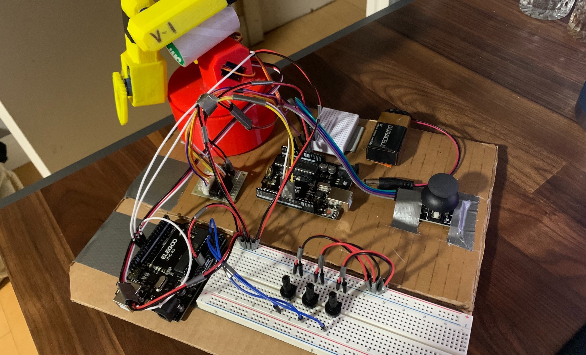
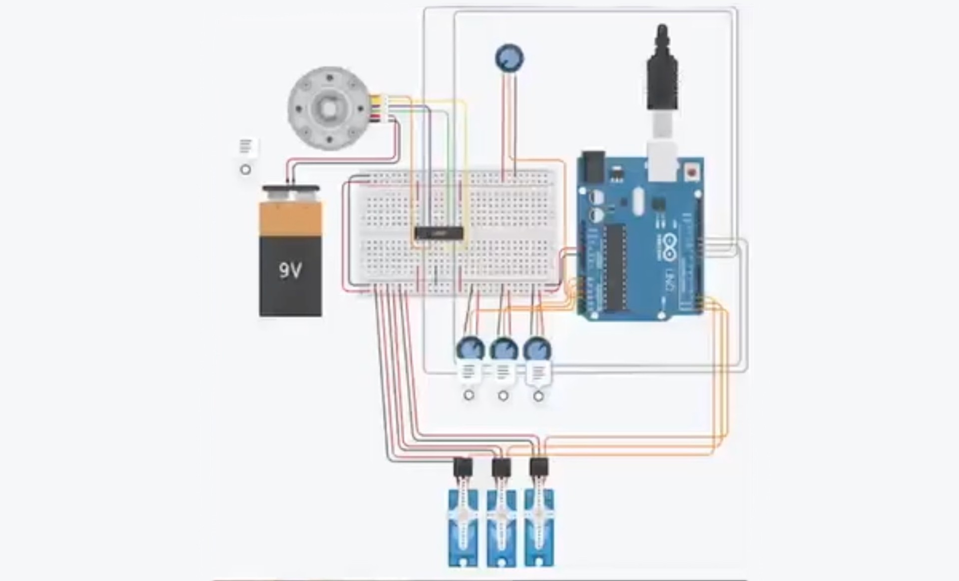
Control was handled through an Arduino-based system that directly interfaced with the servos. I built a simple potentiometer control board to manually adjust each joint angle, mapping analog voltage readings to servo positions in real time.
I started off by reading the potentiometer position in the Serial Monitor, then mapped that input directly to the servo. After some tuning, the motion became smooth and predictable.
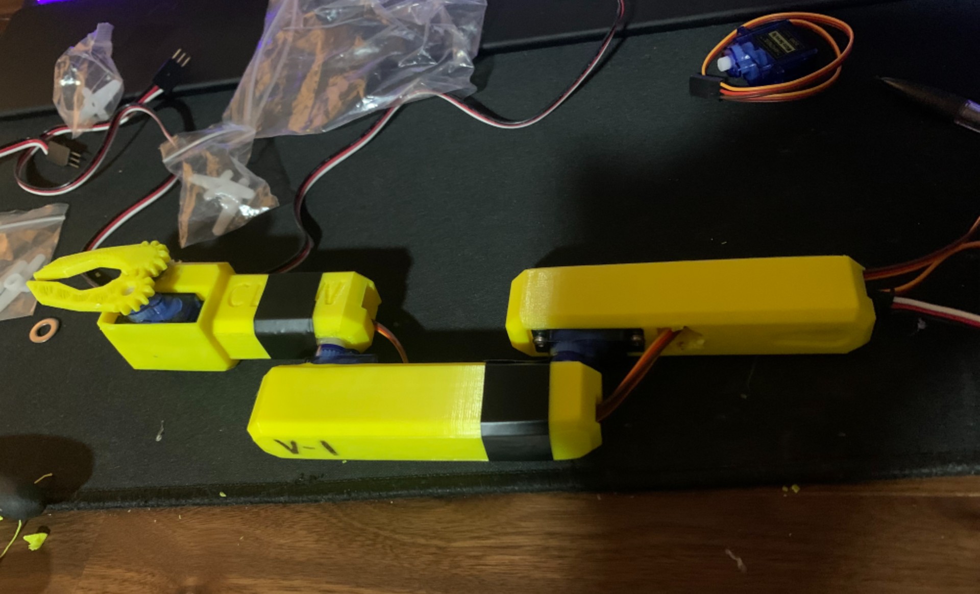
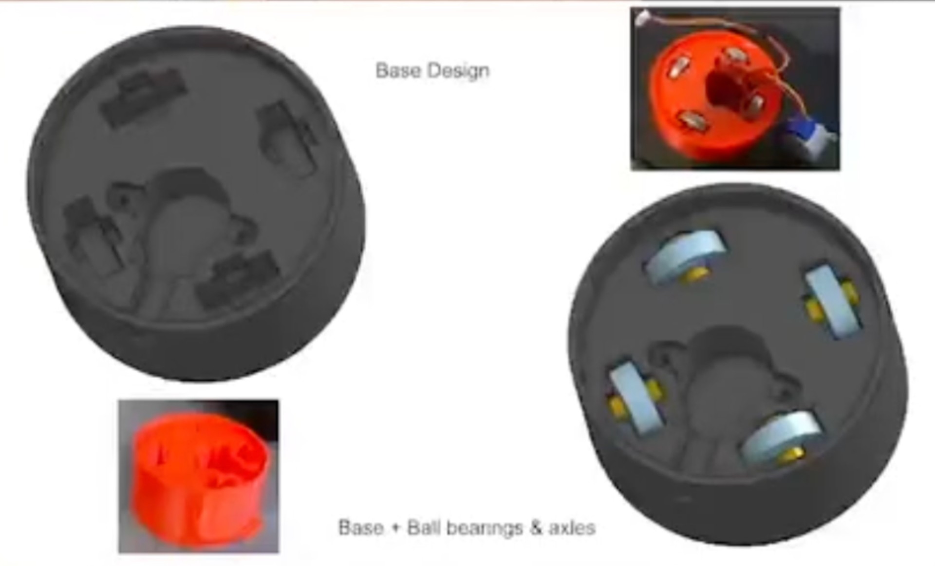
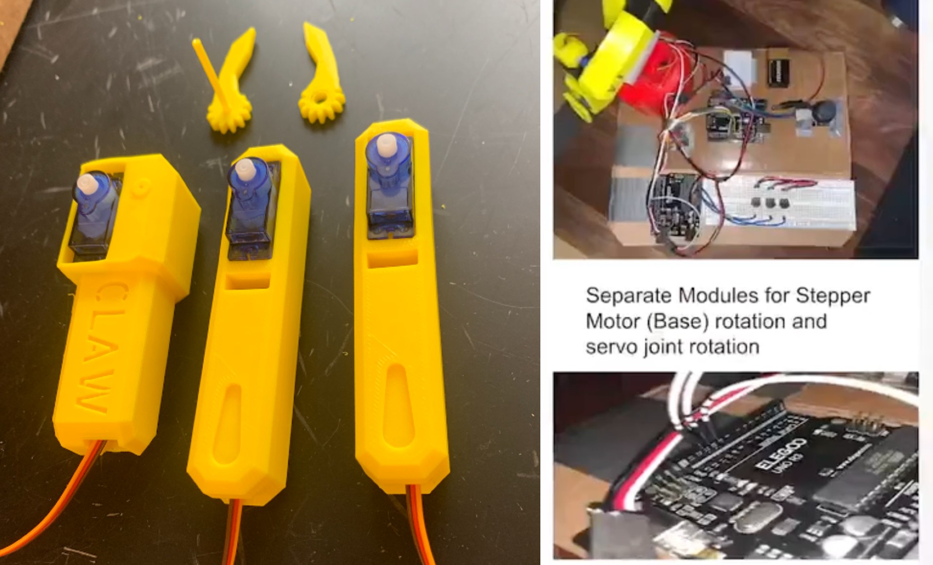
Each joint was independently actuated using servo motors selected based on torque requirements and load placement, with the motors mounted directly into printed housings to keep the build compact. The rotating base was driven by a stepper motor for controlled, incremental rotation. To keep the base stable and reduce wobble, I added small ball bearings that ride around the base, held in place with 3D-printed axles. That bearing ring helped the rotation stay smooth and rigid even when the arm was extended. The gripper used a simple two-finger design to pick up small objects reliably.
Control was handled through an Arduino-based system that directly interfaced with the servos. I built a simple potentiometer control board to manually adjust each joint angle, mapping analog voltage readings to servo positions. This allowed me to experiment with coordinated motion and better understand joint limits and basic forward kinematics.

Overall, this project was a great introduction to robotic arm design and control, giving me hands-on experience with mechanical design, electronics, and programming. It was rewarding to see the arm come together and function as intended after all the planning.